Application case 3:
A Small Darkroom Chamber on the Desk—TEM Cell
foreword
Radiation interference of products is invariably tested in expensive shielded rooms. When you place a car electronic component, only the size of a fist, inside a large shielded room and test it with a huge antenna, do you suddenly find the scene a bit comical? Do you ever have a sudden flash of inspiration: Can I test the component in a scaled-down shielded room?

Congratulations, you got it right! This "scaled-down shielded room" is the TEM chamber (Transverse Electromagnetic Cell). The results of product radiation interference tests using a TEM chamber are directly recognized within the 9kHz-250MHz range by the standard GB-T18655-2018 (GB-T18655-2018 6.6 Radiation Emission of Components/Modules—TEM Chamber Method), without the need for verification through large darkroom testing. For radiation interference tests above this frequency, the standard's prescribed methods can be referenced to extrapolate the results to those of a large darkroom test. If it is only used for EMC re-engineering of products, the TEM test results are sufficient to accurately reflect the changes in EMI of the EUT before and after re-engineering.
Moreover, the TEM chamber can also be used for product immunity testing. The measurement results are recognized by the standard GBT33014.3-2016 within the frequency range of 0.01MHz to 200MHz. For frequencies above this range, it can be used for pre-compliance testing of product immunity re-engineering.
Most importantly, the cost of a TEM chamber is only about 1/50th that of a large chamber and it takes up almost no space, so it can be placed on a desk. Small and medium-sized enterprises can afford to buy and use it.The automatic testing function of the Minilab test system makes testing product radiation interference as easy as using a point-and-shoot camera. Company engineers only need to pay attention to the measurement results and the improvement of the EUT, and do not need to learn complex testing skills.
case
Conduct compliance testing for a product according to GB-T18655-2018 6.6 Radiation Emission of Components/Modules—TEM Chamber Method, and perform pre-compliance rectification based on the test results.
The first step in EMC testing is to set up the test environment and measure the background interference.
Connect the oscilloscope input of the Minilab test system to one of the two ports of the TEM, and connect the other port of the TEM to a 50-ohm RF terminator, as shown in Figure 1(a). Place the EUT and the battery in the space below the partition in the middle of the EUT, insulating them from the metal bottom of the TEM with a high-dielectric constant insulator (e.g., white foam), and try to position the EUT, battery, and the wires connecting the battery and EUT in the center of the lower chamber of the TEM, as shown in Figure 1(b).

(a)
(b)
Figure 1: Test Environment Setup
Disconnect the battery from the EUT, open the mobile app—Minilab test system automatically measures the background interference of the TEM chamber, as shown in Figure 2. Figure 2(a) shows radiation interference in the 150kHz-30MHz frequency range, and Figure 2(b) shows radiation interference in the 30MHz-250MHz frequency range; in both (a) and (b), the horizontal lines represent the standard limit.


(a)
(b)
Figure 2: Background Interference of the TEM
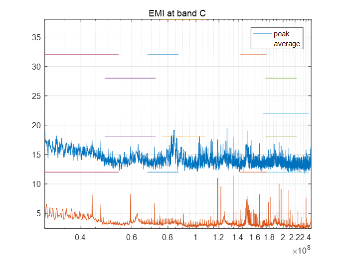
Step 2: Reconnect the battery to the EUT and rerun the Minilab test system. This time, the measurement results show the radiation interference spectrum of the EUT, as shown in Figure 3.
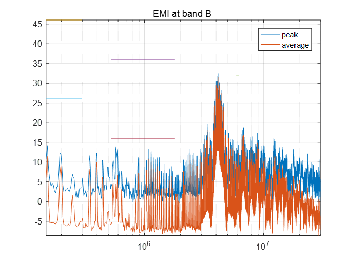

(a)
(b)
Figure 3: Radiation Interference Spectrum of the EUT
Figure 3(a) shows a narrowband interference around the 4MHz frequency, reaching up to 32dB, and the EMI average in the 5.9MHz-6.2MHz range exceeds the standard limit of 12dB.Figure 3(b) shows that the EMI amplitude in the 30MHz-50MHz range is close to the standard limit of 12dB, requiring rectification to reduce it.
Step 3: Trial-and-Error Re-engineering of the EUT
Step 4: Retest to evaluate engineering effectsRetest to evaluate the effectiveness of the re-engineering measures. If the results are not satisfactory, revert the EUT to the state before the last rectification attempt and try different rectification measures. Continue this process until satisfactory results are achieved, as shown in Figure 4.

(a)
(b)
After re-engineering, the EUT passed the radiation interference compliance test.
Figure 4(a) shows that the narrowband interference around the 4MHz frequency has been effectively removed, and the EMI amplitude in the 5.9MHz-6.2MHz range has been reduced to 0dB, providing a 12dB margin compared to the standard limit of 12dB.Figure 4(b) shows that the EMI in the 30MHz-50MHz range has been successfully eliminated. The spectrum above 50MHz is identical to the TEM background noise spectrum shown in Figure 2(b), with no interference detected from the EUT.In summary, the rectified EUT meets the standard requirements.engineer_result_fig4=Figure 4: Test Results of the EUT after re-engineering
Conclusion
After re-engineering, the EUT passed the radiation interference compliance test.
Postscript
For small-sized EUTs, such as automotive electronic products, the Minilab test system using the TEM chamber method can quickly achieve radiation interference compliance testing or immunity testing in the 150kHz-250MHz frequency range on-site.When used for reducing EUT radiation interference or immunity rectification, the MINILAB test system's quick testing capability can shorten the trial-and-error steps. Slight modifications to the EUT circuit can be immediately tested and corrected, resulting in rapid rectification.It is important to note that when the Minilab test system is used for radiation interference reduction rectification, the system's general-purpose oscilloscope can display spectra up to a frequency limit of 250MHz. For testing higher frequencies, an oscilloscope with a higher sampling rate is required. The achievable upper frequency limit for radiation interference testing is determined by the sampling rate of the oscilloscope: the upper testing frequency limit = (1/5 to 1/10) of the oscilloscope sampling frequency. For immunity rectification, only a suitable signal generator needs to be selected.