Finding an appropriate EMC compliance solution - Trial and Error Method
Finding an appropriate EMC compliance solution - Trial and Error Method
foreword
Pre-compliance EMC for manufacturing products includes pre-compliance testing and pre-compliance guide. Pre-compliance is the goal of engineering, while testing serves as the guide of the engineering.

If the product's EMC compliance testing is akin to the final exam, then the pre-compliance testing is like a mock exam. However, "the student surpasses the teacher," and beyond simulating compliance tests, pre-compliance testing also bears the responsibility of "finding an appropriate EMC re-engineering solution," including:
- Finding re-engineering solutions that not only pass compliance testing but also enhance the product's EMC performance beyond standard requirements. Why is it that some automotive electronic products, which all pass EMC compliance tests, work harmoniously with the entire vehicle, while others do not? This is because EMC standards do not fully cover all EMC conditions of the product. For example, EMC standards typically assess the EMC conditions of a product during its typical operation after being powered on. Some products generate significant electromagnetic interference during the startup phase, which is usually not detected by EMC compliance tests, yet in actual operation, this interference can affect the vehicle's control circuits. Pre-compliance testing aims to improve the overall performance of the product by identifying these non-standard detectable interference conditions.
- Finding re-engineering solutions that not only pass compliance testing but are also suitable for mass production. If a product passes the EMC compliance test and obtains certification, but the re-engineering solution is not suitable for large-scale production, it cannot be strictly implemented. Consequently, the final products face significant EMC risks in market competition.
- Finding re-engineering solutions that not only pass compliance testing but also add minimal cost. This is something that executives, especially those focused on reducing product costs, will certainly appreciate.
Below is a case where an enterprise engineer cleverly utilized the Minilab testing system's quick and low-cost features to rapidly find an appropriate rectification solution using the trial-and-error method; it focuses on the use of the Minilab testing system, omitting specific re-engineering measures.
case
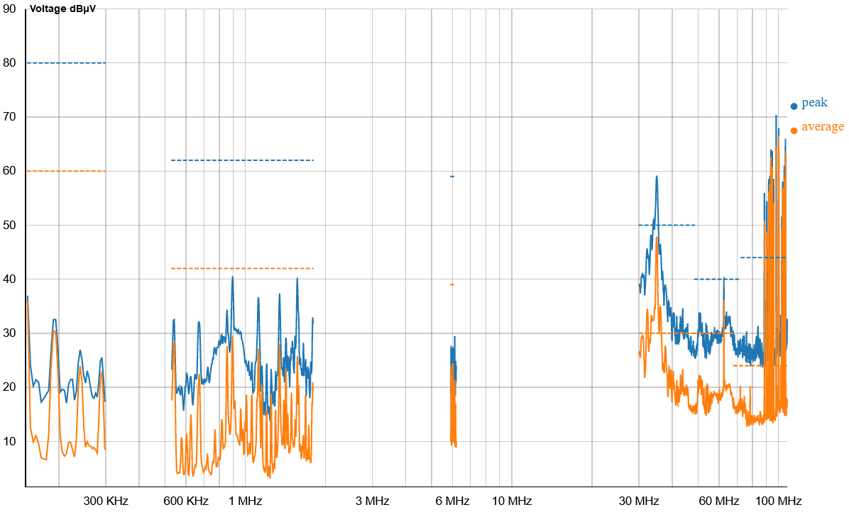
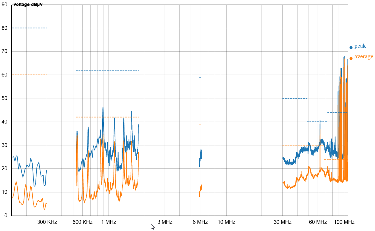
A product underwent compliance testing according to GB/T18655-2018 Class 3 at an EMC certification body, and the conducted interference exceeded the average value limit around the frequency point of 34 MHz.
Step 1: Determine the Suitable Environment: The engineer first determined that their office was a suitable environment for conducting conducted interference tests on the product, laying the foundation for evaluating the subsequent rectification effects.
Step 2: Establish a Golden Sample: The EUT tested in the standard laboratory for the product could not be obtained for some reason. Instead, a sample from the same model was used as the EUT. The engineer used the MINILAB testing system to test this sample in the office and obtained the following results: Test Report Number 2021-06_02101.
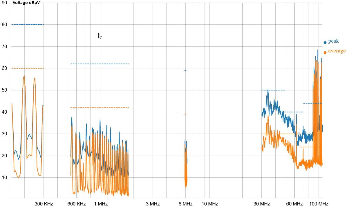
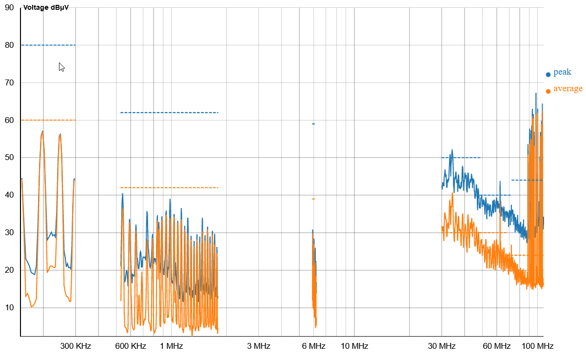
and its quantitative table
Standard Laboratory Test Results:

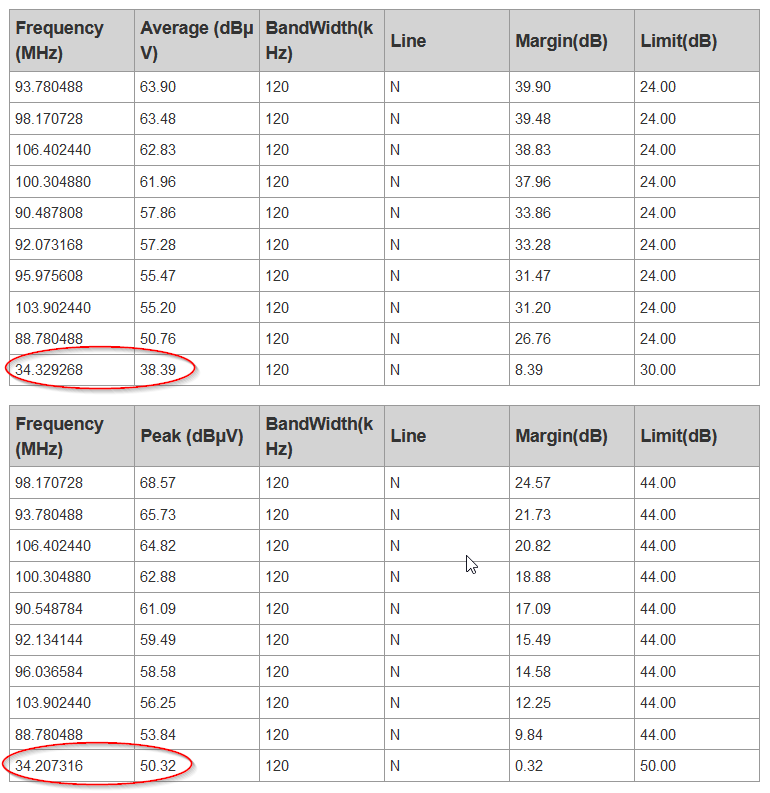
The standard laboratory test results showed that the average value exceeded the limit around the frequency point of 34 MHz. A comparison with the Minilab system test results is as follows:
| Standard Lab Results | Minilab Results | Absolute Difference | Relative Difference | |
|---|---|---|---|---|
| Peak Value(dB) | 49.86 | 50.32 | 0.4600 | 0.92% |
| Average Value(dB) | 39.34 | 38.39 | 0.9500 | 2.41% |
??compare _result_en_US??
Step 3: Find an Appropriate Rectification Solution through Rapid Trial and Error.
Trial and Error Method: Each time, add or remove a component from the EUT or slightly alter the circuit structure. Immediately use the Minilab testing system to measure conducted interference to determine if electromagnetic interference (EMI) has decreased. If the interference increases instead of decreasing, revert the circuit to its previous state before that rectification step and then try a new step. Below are selectively recorded a few steps from the multiple trials and errors re-engineering steps.
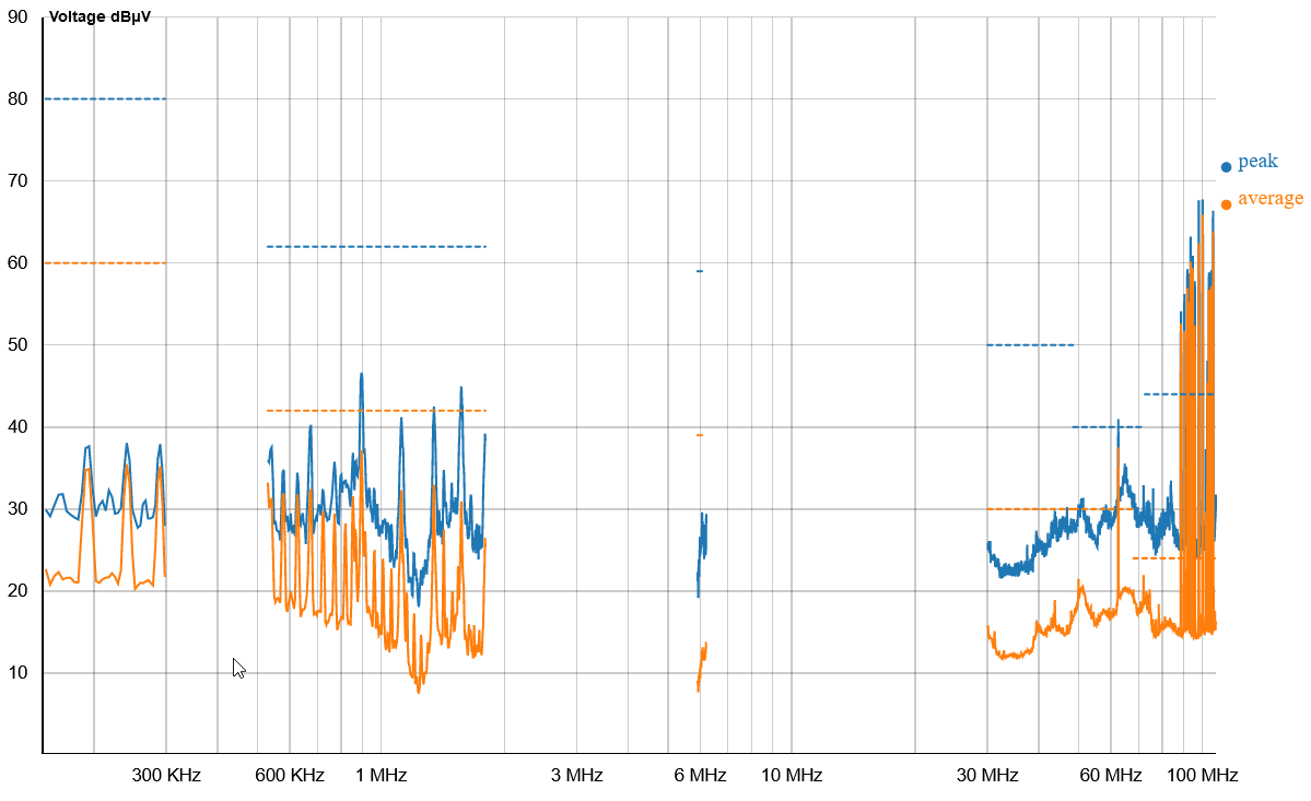
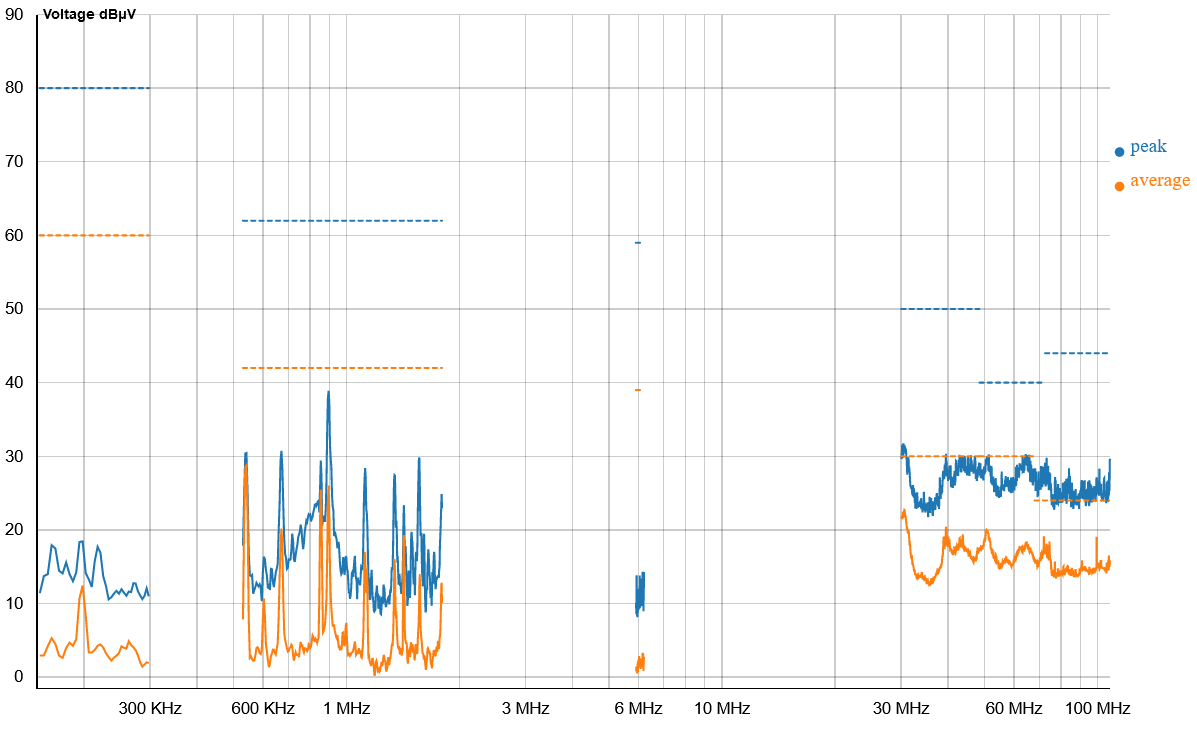
Re-engineering Case 1
The rectification direction was incorrect, resulting in an increase in EMI amplitude at 34 MHz.
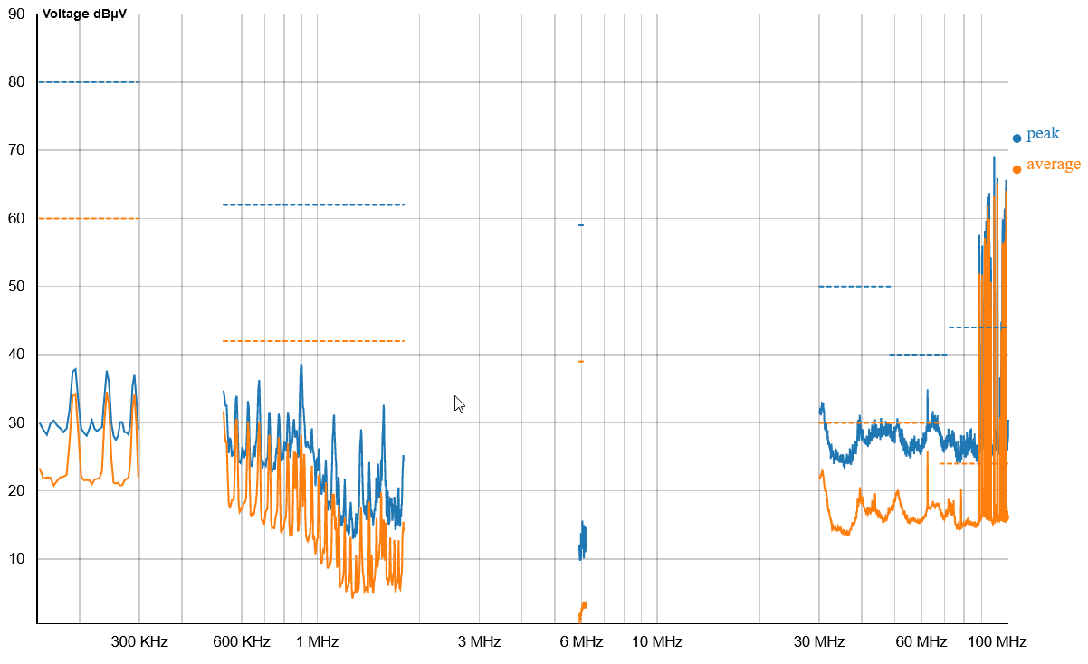
Re-engineering Case 2
Report Number2021-06_02157
The rectification direction was incorrect, and the voltage waveform showed peaks of up to approximately 300mV, increasing the amplitude of low-frequency EMI.
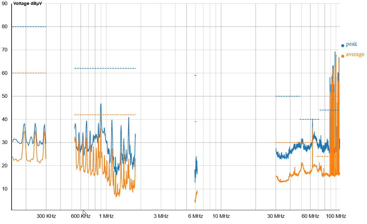
Re-engineering Case 3
Report Number2021-06_02158
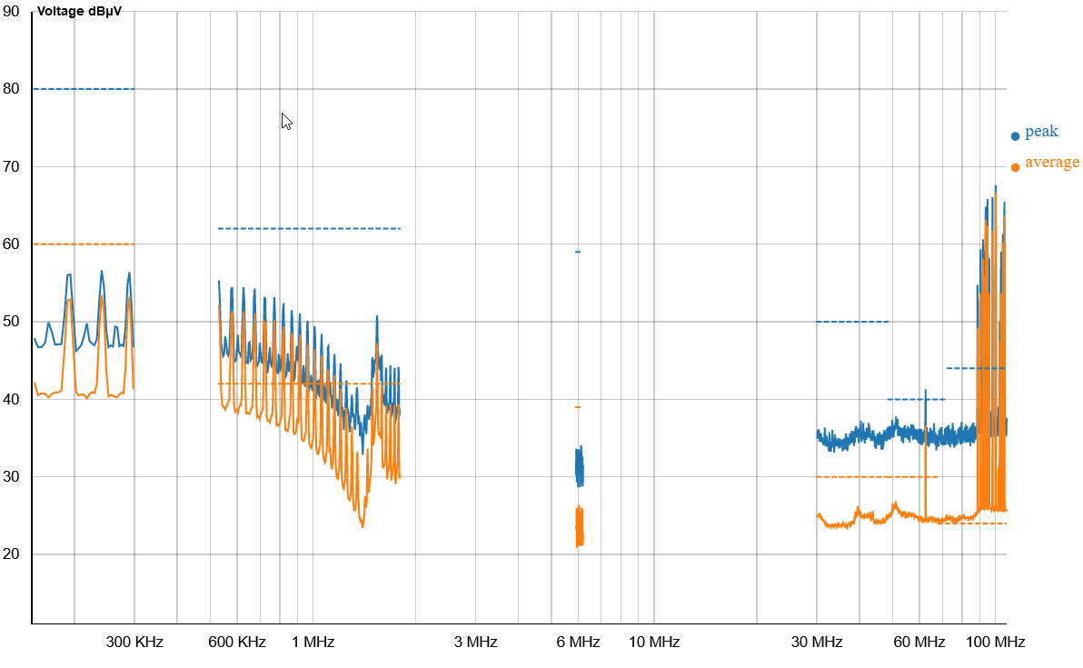
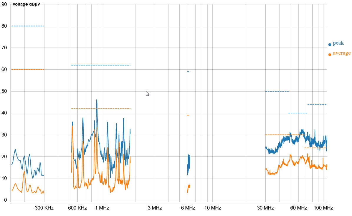
Repeatability test
Report Number2021-06_02160
Repeatability test
Report Number2021-06_02159
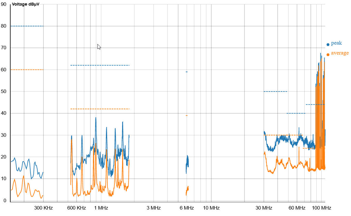
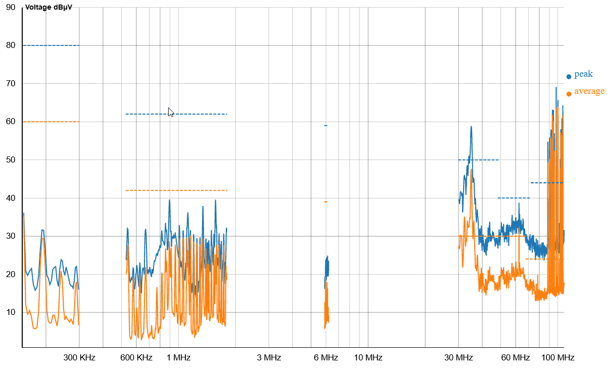
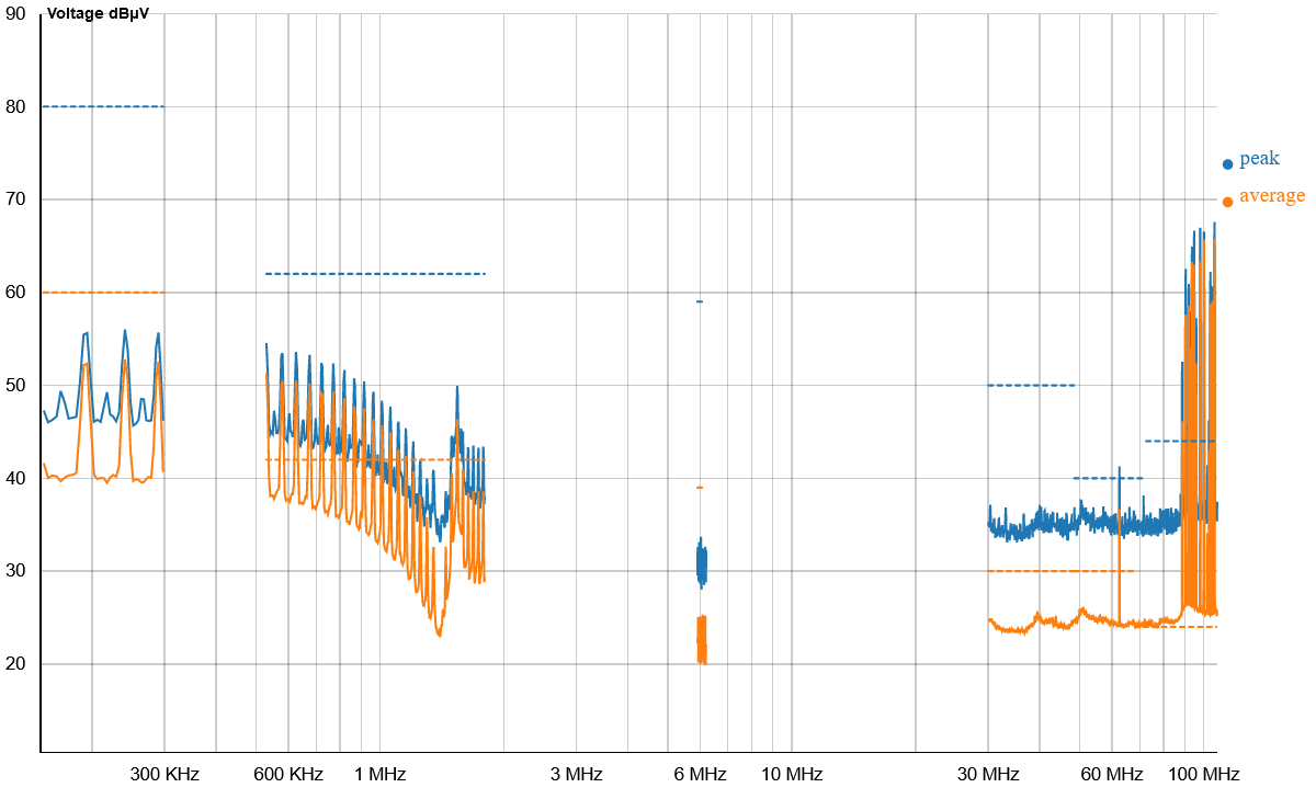
This re-engineering yielded good results. From the start of power-on, continuous measurements were taken three times. As the EUT warmed up, the EMI waveform changed and stabilized after 14 minutes.
Results after using the Minilab's environmental interference removal function to eliminate environmental interference from Test Report Number 2021-06_02159:
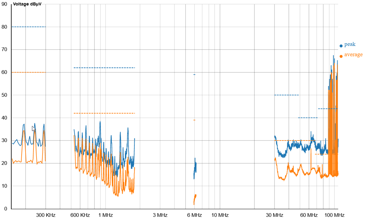
Step 4: Compare the Final Rectification Results with the Golden Sample Measurement Results:
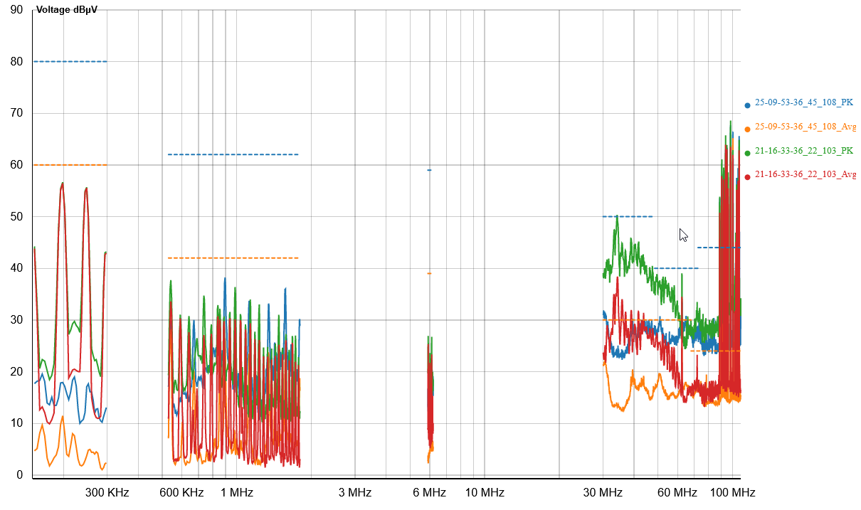
As shown in the table above, after re-engineering, the peak and average EMI amplitude at the problem frequency of 34 MHz decreased by approximately 26 dB. In the frequency range of 30 MHz to 108 MHz, the average value is at least 12 dB lower than the Class 3 standard used by the standard laboratory, and the EMI amplitude in the frequency range of 150 kHz to 2 MHz also decreased.
Conclusion
Following the guiding principle of "Test Environment Electromagnetic Compatibility," conducting frequent rapid tests on products at the enterprise site can effectively shorten the trial-and-error steps of EMC re-engineering and accelerate the re-engineering process. The "golden sample" not only ensures that the re-engineering results align with the EMC laboratory test results but can also be used to calibrate the test environment at any time. If the retest results of the golden sample significantly differ from the preserved golden sample test results, the test environment or test setup should be checked for changes.
Postscript
The trial-and-error method leverages the Minilab testing system's advantages of speed (less than 3 minutes) and low cost (cloud computing services). By making small incremental changes to the EUT and immediately testing and correcting, the trial-and-error cycle is shortened, speeding up the arrival of the final solution. This method is similar to traditional Chinese medicine, where an initial dose of five packets is given, then the prescription is adjusted after a follow-up visit. It is suitable for EMC re-engineering of small electronic component products.For products with larger or more complex circuits, a "Western medicine approach" can be considered. First, use the Minilab guide system's EMI localization to determine the physical location of the interference, then perform targeted re-engineering at the interference location. Subsequent sections will introduce the interference localization methods used to find appropriate re-engineering solutions through application cases.
Minilab's practical application shows that most enterprises can find suitable environments for conducted interference testing within their premises. For those unable to find an appropriate testing environment or whose EUT interference frequency coincides with the environmental interference frequency, it is advisable to consider using a TEM cell to establish a micro testing environment.