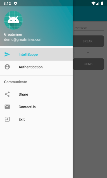
- Install GreatMiner App
- EMC Guide
- Minilab Testing (Conducted Interference)
- Minilab Testing (Radiated Interference)
DIY Product EMC Re-engineering—Pre-compliance EMC for Manufacturing
Product EMC pre-compliance is widely used to reduce the risk of failing compliance tests. Especially when a product fails the EMC compliance test in a standard laboratory, rectifying the product and resubmitting it for testing until it finally passes compliance testing can become a nightmare for company engineers.
When a person gets sick, they see a doctor. However, when a product exceeds interference limits, it is difficult to find a "doctor" for the product. If the company's product rectification is urgent and budget is not an issue, a third party can be commissioned to handle the rectification. However, after adding numerous inductors or shielding measures and eventually passing the EMC test, you might find that the rectified sample is not suitable for large-scale production or its reliability has decreased. In reality, the best "doctor" for product EMC rectification is the company's own engineers. They understand the product design and can balance production costs, manufacturing processes, and reliability in the EMC rectification plan. Pre-compliance EMC for manufacturing involves the company's engineers leading the product rectification to achieve solutions that pass the EMC test without significantly increasing costs and are easy to manufacture.
The cloud-based Minilab boon for company engineers dedicated to solving product EMC issues themselves, serving as a powerful tool for pre-compliance EMC for manufacturing. The " Minilab Testing" feature is used to perform preliminary EMC testing on the product at the production site and to evaluate the effectiveness of each rectification. The " Minilab Guide" feature helps locate the sources of electromagnetic interference in the product, enabling targeted rectification of the interference sources and avoiding the trial-and-error maze of traditional rectification methods.
Minilab, as a new pre-compliance EMC tool for manufacturing, has unique application methods and guidelines:
- Methods for Electromagnetic Compatibility (EMC) Testing in Environments with Inherent Interference.
- Golden Sample Method: Seal an EUT that fails testing at a certified EMC institution and use it as the golden sample. Select other EUTs for rectification and compare them with the golden sample at any time.
- Worst-case Measurement Criterion: Always measure the EUT's worst EMC condition and perform rectification based on the worst-case scenario.
- ROLLING BACK Criterion: Evaluate the contribution of each rectification step to the product's EMI. If a step increases the EMI, revert the EUT to its previous state (ROLLING BACK) and then take other steps.
The following Case Study 1 will demonstrate how to find a "suitable EMC testing environment" within a company.
The following Case Study 2 will demonstrate how to use the Minilab testing system to quickly find a "suitable rectification solution."
The following Case Study 3 will demonstrate how to conduct EMC testing on-site at a company using a miniature shielded room (TEM cell).
For products with large-area PCB layouts, we will introduce the use of the MINILAB Navigation system in subsequent case studies.
Finding the right EMC pre-compliance program - trial and error method Read More...
Radiated EMC pre-compliance program - TEM method Read More...
Find a suitable EMC test environment Read More...
Cloud Computing Assisted EMC Compliance—Re-engineering Case Study
Principle of Cloud Computing Assisted EMC Compliance:
If a new product's test results from a standard EMC laboratory indicate that the product (EUT) exceeds EMI limits at a specific frequency, causing the product to fail EMC compliance.
- Utilize the virtual workspace to directly locate and reduce EMI in the time domain, following these steps:I. Select the frequency where EMI exceeds the limit based on the standard EMC laboratory test results, or perform spectral analysis on all measured data to determine the EMI frequency. Cloud computing will automatically calculate the EMI intensity at each test point for the selected frequency and display it as a heatmap. II. Move the mouse to a test point on the virtual workspace to dynamically display the original waveform at that point and its EMI variation over time. III. Adjust the parameters of the product circuit board (e.g., adding/removing components, changing wiring), retest, and upload the electrical signals of the test points. Repeat steps I and II to observe if the EMI has been reduced.
- Utilize the system's "EMI Evaluation" feature to comprehensively check the product's EMI status.
- Repeat steps 2 and 3 until the EMI is reduced to below the allowable limit.
Application case 1:
Product (EUT) requiring re-engineering

Take a photo of the control circuit board and upload it to the cloud to establish the product's "virtual workspace." Mark several test points (yellow dots) on the virtual workspace and use an oscilloscope to test the voltage waveforms at these points.

Use cloud computing to analyze the data from all test points on the virtual workspace to assess the level of interference.

All test points are shown in red (the redder the color, the more severe the interference), similar to a positive nucleic acid test, indicating severe interference. Additionally, all the test points are on the 12V power line of the switching power supply and have a consistent color, suggesting that the interference is unlikely to come from an integrated circuit near any particular test point. It is very likely caused by the 12V output voltage of the switching power supply. Moreover, from the conducted interference measurement results of the EUT:

The marked portions of the spectrum are concentrated in the 150KHz-800KHz range, indicating broadband interference. The large difference between peak and average values suggests that the interference is related to the diode rectification mechanism. Therefore, the diagnosis is as follows:Diagnosis: The output of the switching power supply on the circuit board contains significant broadband noise.Solutions are as follows:Option 1: Adjust the design of the switching power supply.Option 2: Add a filter circuit at the power input.Compared to Option 2, Option 1 increases the per-unit product cost less and reduces the potential for causing radiated interference.
- Step 1. Check if you are logged in.
- Step 2. Check if you have granted the APP required permissions.

- Step 3. Check your network connection.
??faq.retport.more_en_US??Read More....
A: registered user may use workspace at website for EMI detection and reduction. Read More...